

3-Part Series on Installing Motorcycle Heated Handgrips; In-Bar Style, Undergrip Style, Built-In Grip Style
Part 1. In-Bar Style Heated Handgrips Installation
There are several options for heated grips. Three come immediately to mind. Undergrip (read how to install this style of heated grips below); the kind where you wrap some heating elements beneath the rubber handgrips. In-Bar Style; the kind that can be threaded through your bars and be completely hidden, (which we’ll cover first). And the grips themselves; a style where the heating elements are built into the rubber of the handgrip.
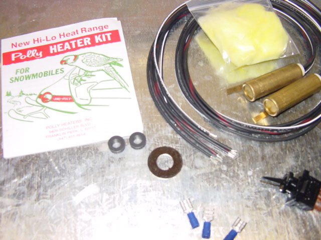
I had never heard of, nor thought of, Snowmobile heated grips. This style features two metal plugs that reside inside the metal handlebar itself. The advantage of this system is that no wires are exposed – and on motorcycles with a twist throttle no exposed wires means that the wires and connectors are not subjected to continuous movement.
To make the grips look OEM installed, we wanted to make every effort to hide as much of the installation as possible. Starting out with an M900 Ducati Monster we decided to dive in. NOTE: These heated grips will have compromised performance if installed inside an aluminum bar. We only recomend these if you have a steel bar. If you have an aluminum bar, check out the alternative “wrap-around” heated grips.
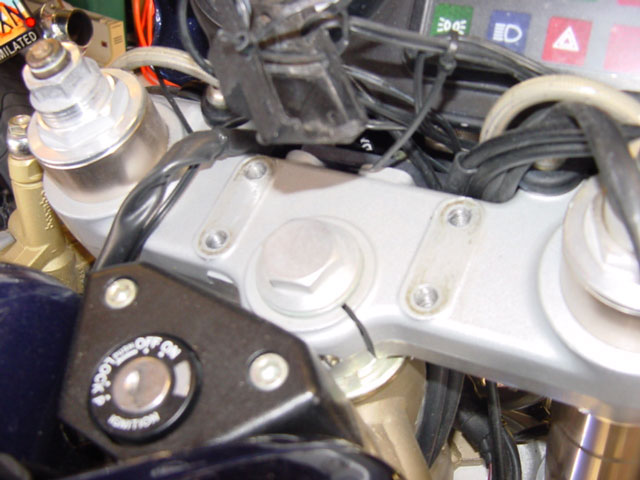
We started by removing the handlebars and the dog bones/risers to see what we had to work with. We were expecting a conventional bolt-through setup, but the Ducati was actually easier to work with, even though it would require more precision.

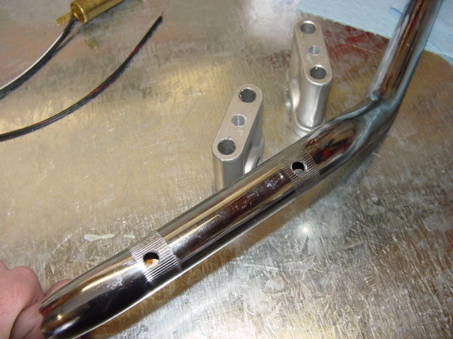
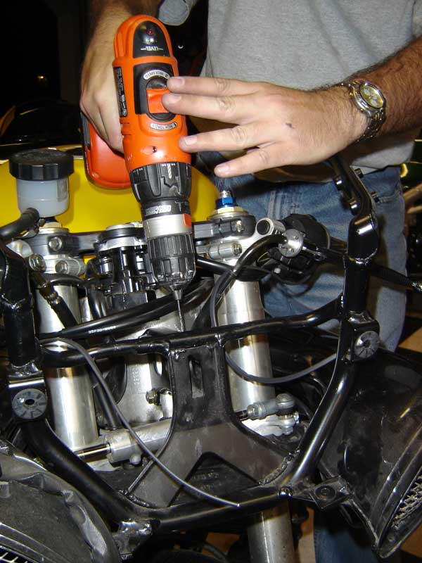
Our biggest concern was drilling down the center of the risers. Too far to the left or the right and We’d end up with some really ugly aluminum. After carefully drilling down the center of the risers, with the smallest drill bit that would allow the wires to pass through, we were ready to move on to the next steps.
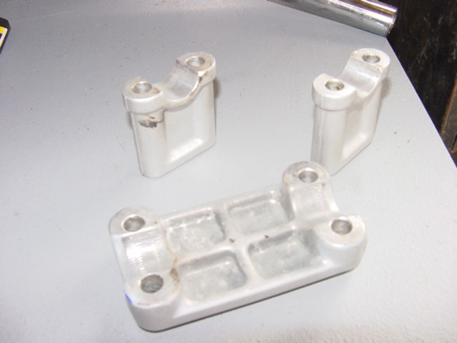

Next we drilled the triple-clamp. Initially we were going to remove the clamp to drill it on the press but then we thought duh, why not just use the risers like a template. Which is what I did. Bolting the risers back to the triple-clamp we were able to start the hole in the exact right place with just a hand drill. However, it was critical to make sure the risers were labeled so the holes matched up correctly. We were using such a small hole for the wires to pass through that even a millimeter offset could pinch the wires and tear the insulation.


Using the same method we used for the triple-clamp, we drilled the handlebar. This proved to be quite a bit harder because everything kept moving around. We had to make sure we held the risers in the exact right place otherwise the preferred handlebar position would be tweaked or the two holes would be offset from each other. We marked the handlebar position with a sharpie before removing it so there were some reference marks. We ovalized the holes to allow for some adjustment of the handlbars, being careful not to make the holes too large and compromise the strength of the bars. Aluminum bars are thicker and will require additional modification to get the grips to fit inside.
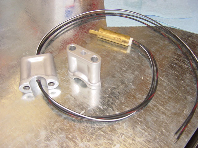
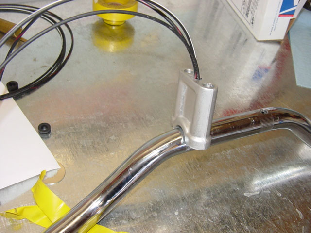
Pulling the wires through the bars proved to be much more difficult than expected. It took a fair amount of time and quite a bit of patience to slowly grab the wires with some tiny hooks and awls.

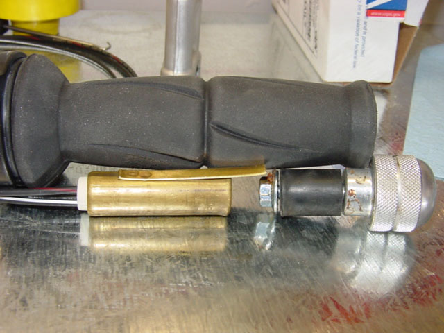
All along we were worried about having enough room for the bar-end weights or bar-end mirrors. Fortunately, the plugs are small enough to allow for plenty of room for both and allowing for optimum placement of the heating element, which would be closer to the inside of the hand position. Cleverly, the kit comes with some fiberglass insulation that goes into the bar before the heating element. This prevents the element from moving and keeps the heat where hands will be.

Putting everything into place proved to be the most difficult part of the task. Moving everything in unison without pinching wires was tedious and difficult. Every slip meant starting over again. A simpler installation would have prevented this part of the installation, but a job worth doing…
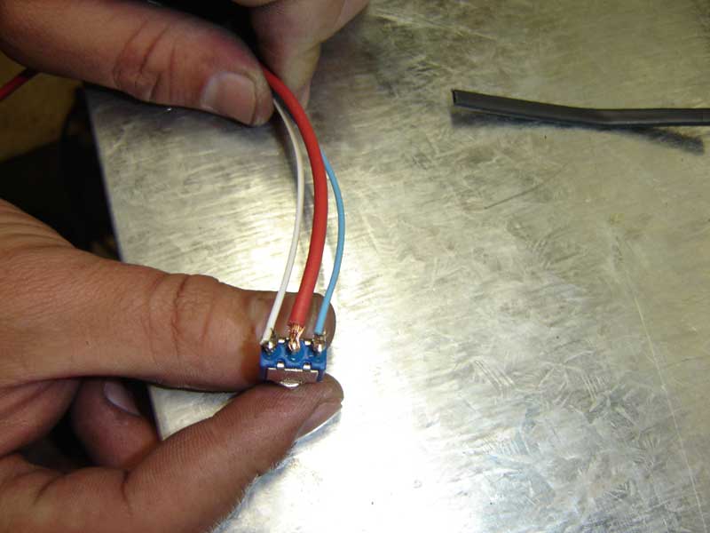
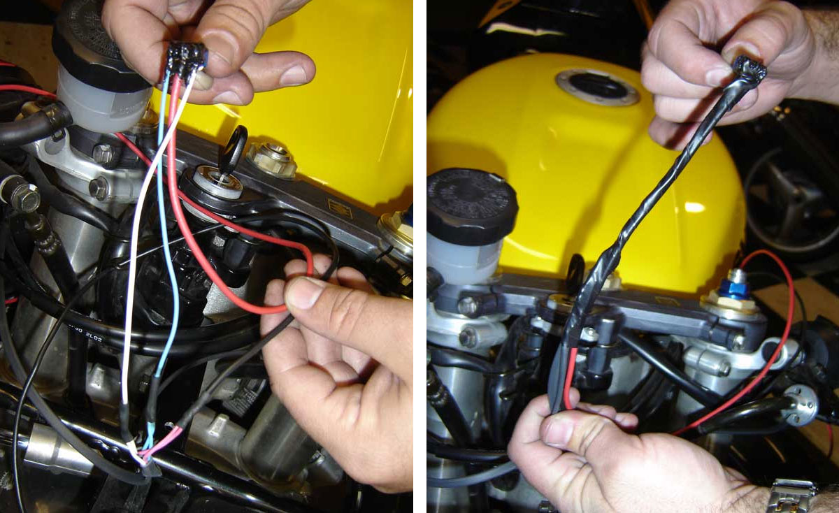
The gargantuan switch that came with the kit is really ugly so we replaced it with a much smaller switch with the exact same specifications. The wiring diagram in the package is somewhat cryptic. The wire with the red line is “high” the all black wire is”low” and the wire with the white line is the ground. You’ll need to provide your own red wire to run to a positive lead.

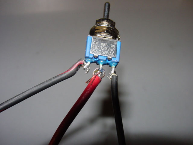
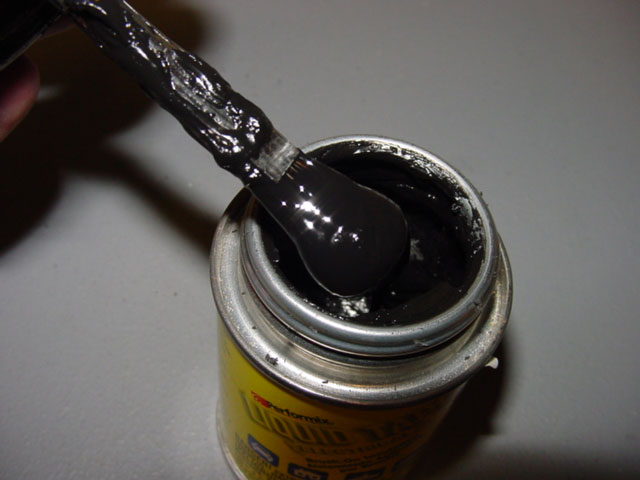
Solder everything. We’ve had too many bad things happen with solderless clips. We also used liberal amounts of liquid tape. Liquid tape is a nasty black goop that you brush onto an exposed connection and it dries to a black rubber. Use the liquid tape to weatherproof the switch as much as possible.
Twist and tape the wires to make them look a bit neater and if you look close you can see the liquid tape “weatherproofing” on the switch. Used some heat shield around the leads of the switch to ensure there will be no accidental shorting.
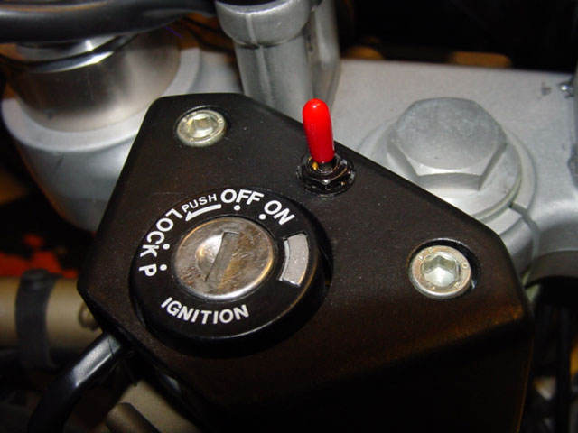
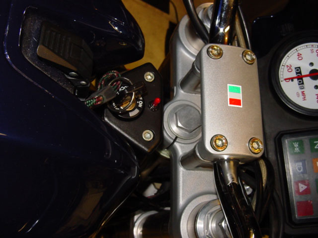
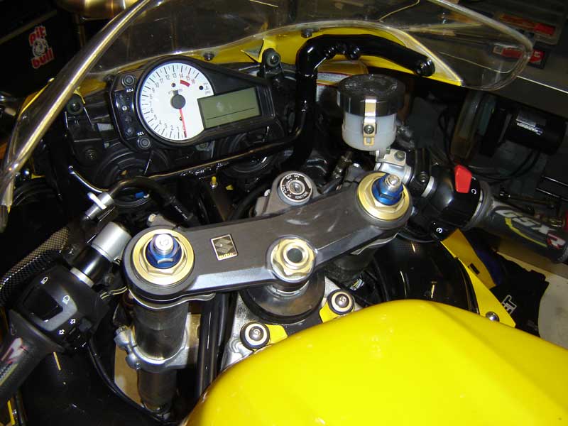
Another quick trip to the drill press and we were able to make for a very tidy switch location. We used a little bit of flat-black model paint to mask the silver bolts and washers holding the switch in place. The switch also came with four rubber boots that cover the dongle of the switch to keep out moisture and make the dongle easier to handle with gloved fingers. The covers come in white, yellow, green and red. Its a Ducati, so we had to choose red. We do wish there’d have been a black option. That would have been stealth.


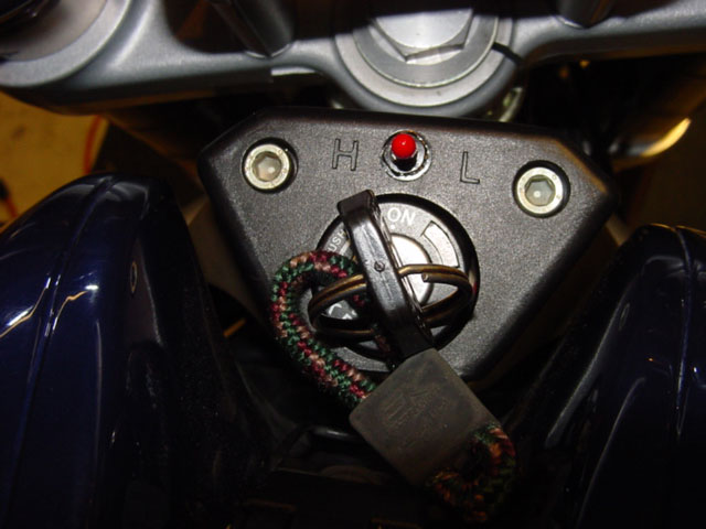
The switch position will be opposite of the wire locations. If the wire attaches to the left lead of the switch, high will be active when the dongle is moved to the right. I also used some black vinyl lettering to mark the high/low positions, adding that last little touch. Wire the switch up to a relay, so that when the key goes off, the grips turn off as well. This will prevent accidental battery death by a forgetful pilot or meddling passer-by.
NOTE: A relay/distribution-block allows the rider to hook up multiple items at one place and have the all the accessories turn off with the key. A relay/distribution block typically runs directly off the battery with the relay getting its power from a running light or other switched source. Because the relay has virtually no draw, there is very little risk of overwhelming fuses. And because the distribution-block, and all the accessories, gets power directly from the battery there is very little chance for damage to other electrical components.
Also, most bikes generate far more electricity than the bike needs; enough to have the ability to run two heated vests and a set of heated grips without putting any undue strain on the electrical system. However, every bike is different and you should check to be sure your bike can handle the added electrical workload. We’ve yet to find any bike that did not have a strong enough alternator to handle heated grips. On almost all of the CanyonChasers bikes, we run heated grips, up to two heated vests, GPS devices, MP3 players and radar detectors – all at once – and have never had any problems. Mikey has even set up a way to charge camera and phone batteries and has never run into any problems.
The grips put out an astonishing amount of heat, but does take a bit longer to warm up the metal handlebar and the rubber grip. The grips put out so much heat that even with the bike just idling in the high position it was almost too hot to touch with bare hands. With gloves on and exposed to cold temperatures the heat is dampened a bit, but the in-grip heaters work so well that we found we rarely used the grips in the high position. For almost every situation the low setting was just about perfect. Another benefit of the in-bar heaters, as opposed to the undergrip heaters, is that while they take longer to warm up, once warm they stay warm for longer. They also produce a more consistent heat between the thicker throttle hand and the less bulky left hand.
Part 2. Undergrip Heated Handgrips Installation
So, you are more than just a fair weather rider, or you ride in an area, such as Utah, where a days riding could send you from triple-digit heat to snow-on-the-side-of-the-road cold. Carrying multiple pairs of gloves is a pain, besides you have to stop to swap them out, and if it warms up, you have to stop and repeat the process all over again. I hate that. But I also hate cold hands. So unless you own a bike that came from the factory with heated grips you suffer through it, right? Wrong.
Any bike can have heated grips fitted for less than a good pair of warm riding gloves. Plus, you can turn them on or off at whim. Adding heated grips is something that we can do to all of our bikes! Few things are as nice as riding along the coast or a mountain pass, the temperature drops and to combat it, simply reaching for a small toggle and choosing either high or low for your hands happiness. Surprisingly, having warm hands makes a much bigger difference on overall comfort than you would think.
But installing heated grips sounds hard, and you’ll have to monkey with your bikes wiring. Well, never fear! We’ve assembled a step-by-step, with pictures to help walk you through the process.
We’ve already detailed the installation of in-bar heated grips, but they won’t work on bikes with clip-on handlebars. So this is a much cheaper under-grip heated grip system that still allows you to use whatever hand-grips you prefer.

The kit comes in a couple variations. An ATV version that warns against installing on motorcycles and a motorcycle-specific version that costs a few dollars more. We’ve purchased both and have found the only difference to be throttle/clutch specific heating elements on the motorcycle-specific version. This is done to facilitate the fact that your throttle side handgrip is thinner than the clutch side handgrip because of the plastic throttle tube. Oodly, the motorcycle-specific version cost, in our case, $10 more than the ATV version. Additionally, unless you are really persnickety about both hands warming up at the same rate, we saw no advantage to the motorcycle-specific version. In fact the clutch side heating element appears to output less heat than the ATV version. So, in other words, just buy the ATV version and save your beans.
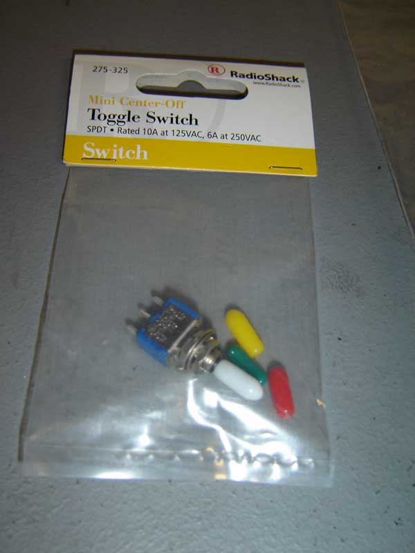
The kit contains all sorts of additional bits that you’ll just throw out, including a yellow wire, some male/female wire clips and the largest three-way switch known to man. The three-way switch would be enough to discourage most aesthetic conscious motorcycle owners who do not want the look of their svelte bike marred by a huge switch. However, a quick trip to Radio-Shack (“ You’ve got questions, we’ve got blank stares” ) for a mini center-off toggle switch will solve that. The one’s we’ve had good luck with comes with four colored switch sleeves and have a higher rating than the switch that comes with the grips. I also purchased some decently high grade red and black wire. In essence, after your trip to Radio-Shack the only part of the heated-grip kit that you’ll keep will be the heating elements themselves. That’s okay.
Before I start, I like to spend a fair bit of time with a cool beverage of choice looking at the cockpit of the bike that’s getting the heated grips. This is to give me ample time to think of places to put the three-way switch. I put the switch on the speed triple in the bracket that holds the meters on the bike and Mikey put his switch inside his left switchgear housing (that’s a lot of work for someone lazy like me). Eric actually purchased a handlebar-mount switch for his 919. Every bike will be different, and the fun part will be deciding where to put the switch.
Once you decide, you can start disassembling the bike as needed to gain access. Naked bikes are easy as very little has to be removed and the job can be done is about an hour. Full-faired bikes, like our donor-cycle GSX-R 750 required full bodywork removal. In fact, we spent more time removing all the body work than we did actually installing the grips.

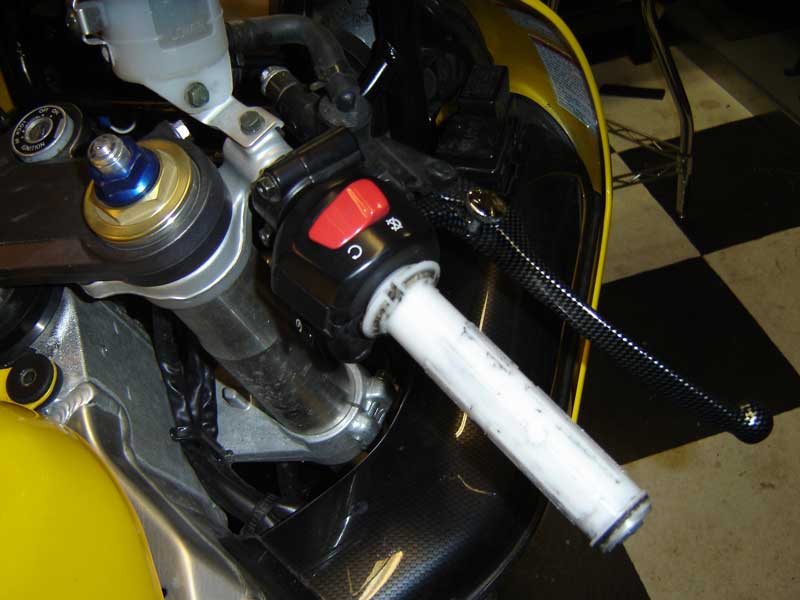
First, remove both handgrips. Compressed air makes this a lot easier as you can just burp them off the bike. The clutch side is really easy, but the throttle side will require a bit more finesse because the plastic throttle tube has nubs to hold the grip in place.

The heating elements have sticky backing. I like to install mine with the seam/gap just below where the heel of my hand will be during riding. Also, be very careful with the wire. They need to be towards the switch-gear, but too much manipulation could result in damaging the heated-grips. Again, the clutch side is easier because you do not need to worry about the grip needing to rotate. NOTE: If you have aluminum bars, you may want to put a few wraps of black electrical tape around the aluminum on the left side of the bar (non-throttle hand), then install the heating elements on top of the electrical tape. Aluminum is a very efficent conductor and will heat-synch a lot of the heat away. This is more important with tube-style handlebars.
After I affix the grips, I like to wrap the lead wires one-around the handlebar then secure them in place with a wrap or two of black electrical tape. This prevents any unnecessary movement and potential damage to the wire leads. I also like to leave the wire tail hanging straight down towards the ground.
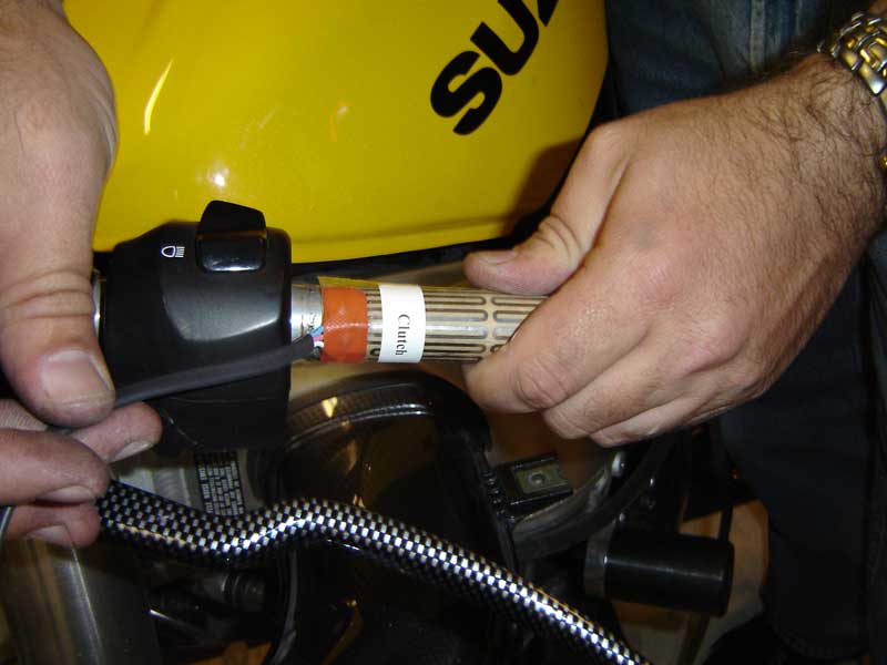
Once you have the heating elements in place, loosely route the wires where you’d want them to be. I try to run mine along existing wires/cables. If you are careful and thoughtful, you’ll never notice the wires are even there. Also, be sure that you have plenty of slack on the throttle side to allow for full throttle movement. Check and double check by twisting the throttle and releasing with the handlebars tuned full lock to the left and the right to ensure there is no binding!

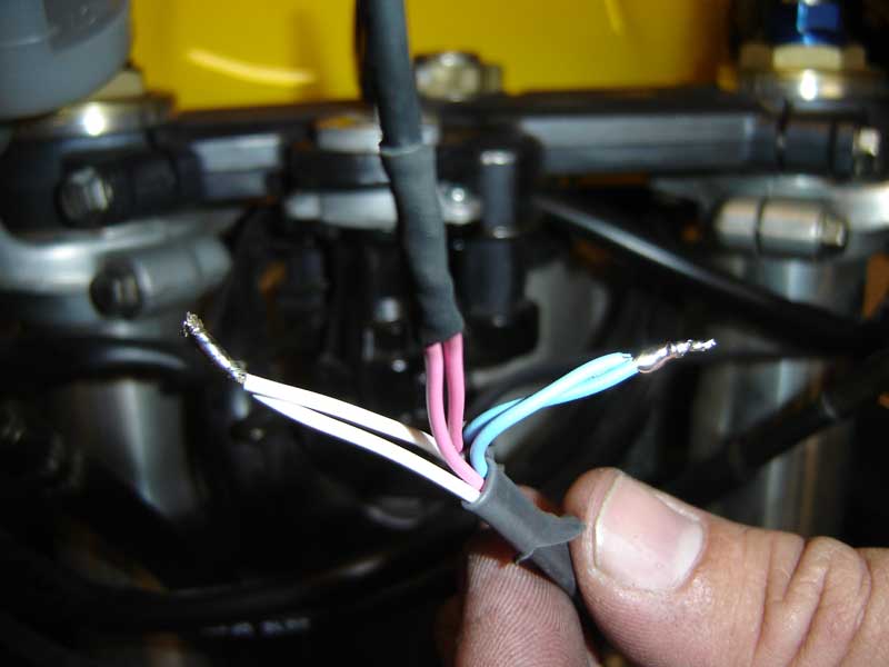
Then the wiring part; each grip has three wires going to it. Typically there will be a white, a blue and a red wire. Because you have already loosely routed your wires, you’ll know how much wire you’ll need. I like to try to keep both wires a close to the same length as is reasonably possible. Then connect the two sides together; white to white, blue to blue and red to red.
Then take out the switch, and since you know where its going to be located, you’ll know how much wire you’ll need there too. This is also a good time to make any modifications to the bike for you to install the switch. On our GSX-R, we found a great location in the center of the fairing stay that allowed for subtle wire routing and easy access to the switch.
A quick note on how the switch works. The center position is off, and if the switch is toggled to the left, it will connect to the lead on right. Conversely, if it is in the right position, it activates the left lead. This is good information so you’ll know which way will be high and which way will be low-heat and will be able to install the switch how you want. I tend to prefer switching the left for low and to the right for high.
Solder three wires to the leads of the switch. The center post of the switch will be the positive connection. This is why I like to use my own red wire. In this picture you can even see how my red wire is of a thicker gauge than the two side wires. Once all three wires are soldered in place, I like to use liquid tape to really goop up and somewhat weather seal the bottom of the switch as much as I can, as well as prevent accidental shorts.
Back to the wires on the bike; the red center wire becomes the negative or ground wire. This is where I like to use my black wire to avoid all confusion. The two red wires become one solid black wire.
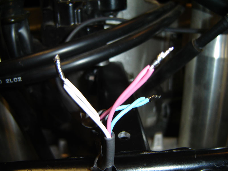
From here, wiring gets easier. Connect the blue wire to the blue, the white wire to the white. I like to use copious amounts of solder and then heat-shrink all of my connections to prevent accidental shorts or moisture from getting into my connection. Besides, it looks a lot cleaner than electrical tape.
WARNING: Some people have thought it to be a good idea to connect the high and low circuits of grips together, so that when they are set to high, both heating elements are active. In every case, this has been met with disaster! Either the wire leads get too hot and melt, or they build up so much heat they melt the handgrips and have even burned hands. I can assure you, the high setting is plenty hot and in most cases, the high-setting is too hot for most riding conditions. Wire your grips appropriately for best results.
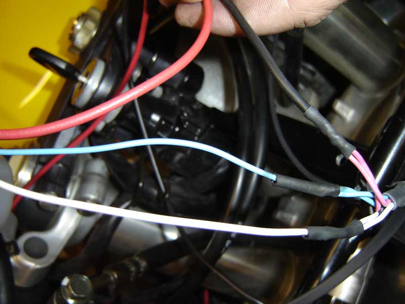
Once all the wires are soldered and sealed, I like to take black tape and wrap the whole thing into single lines. This makes things cleaner and easier to keep track of. I also like to route my black and red wire underneath the gas tank towards the battery.
Optimally, a relay is the best way to go for accessories. That way when you turn off the key, the accessories turn off. Connecting directly to the battery can result in accidentally leaving the accessory on and coming back to your bike to find a dead battery. If you do not have a relay, or don’t want to mess with a relay, you can connect your red wire to just about any wire that is live when the key is on, and dead when the key is off, such as the license plate running light. Just be warned that you may overwhelm the fuse for whatever you hook up to; which is why a relay and distribution block is the best option.
However, I would advise at hooking up the black wire to the negative battery terminal for best results. I would also advise against hooking up the red wire to any major component like your ECU/Brain-box or Fuel Injection system.
NOTE: A relay/distribution-block allows the rider to hook up multiple items at one place and have the all the accessories turn off with the key. A relay/distribution block typically runs directly off the battery with the relay getting its power from a running light or other switched source. Because the relay has virtually no draw, there is very little risk of overwhelming fuses. And because the distribution-block, and all the accessories, gets power directly from the battery there is very little chance for damage to other electrical components.
Also, most bikes generate far more electricity than the bike needs; enough to have the ability to run two heated vests and a set of heated grips without putting any undue strain on the electrical system. However, every bike is different and you should check to be sure your bike can handle the added electrical workload. We’ve yet to find any bike that did not have a strong enough alternator to handle heated grips. On almost all of the CanyonChasers bikes, we run heated grips, up to two heated vests, GPS devices, MP3 players and radar detectors – all at once – and have never had any problems. Mikey has even set up a way to charge camera and phone batteries and has never run into any problems.

Once everything is done, you get to button things back up and take the bike out for a ride. If you took your time and were thoughtful about component placement, you and more importantly your riding cadre will have a hard time finding any evidence of your upgrade. But your hands will know!
Part 3. Built-In Heated Handgrips Installation
Why bother?
Because cold and wet weather plays hell with any body parts that aren’t insulated. And when it does you’re on dangerous ground: reactions get slow and tiredness quickly engulfs you. It’d be impossible to control a bike with gloves that are two-plus inches thick – unlike your upper torso – so heated grips are excellent at stopping your hands from freezing. Today’s modern heated grips look no more out of place on a bike than the seat.
What you’re dealing with
A pair of replacement handlebar grips made of rubber and laced with wire elements. Both grips wire directly to the bike’s battery, sometimes with an electronic thermostat in line to control the temperature range.
Don’t think about it if…
…You have panic attacks about fitting a three pin, 240v mains plug, or a phobia about working for more than an hour.
Stuff you’ll need
A sharp knife and contact cleaner to cut and remove the old grips. A tin of contact adhesive if the heated grip kit doesn’t come with any form of glue to fix the new grips in place – or hairspray works jut as well. An assortment of combination spanners (ideally 8-19mm), or Allen keys 5-10mm to remove the fuel tank and hide the wiring. Phillips (cross-head) or Pozidrive screwdrivers to remove handlebar end-weights and loosen the battery terminals.
What can go wrong?
You might slash, or glue, your hands together, blow a fuse by wiring it all up to the wrong terminals… but only if you attempt the job while drunk.

1. Check all components are enclosed according to the parts list and make sure there are instructions in case of probs. Locate the grip for the throttle side – it has a bigger internal diameter to fit over the plastic throttle tube holding the throttle cables. You really don’t want to spend all day trying to force the narrower clutch side grip on to the throttle tube…
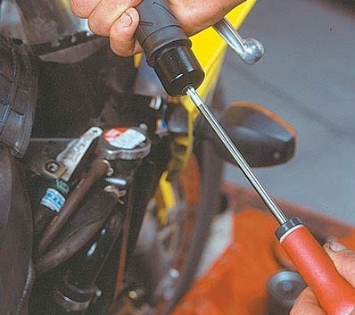
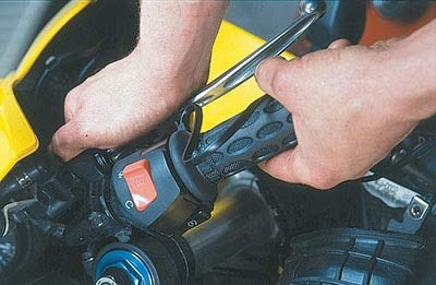
2. Remove the bar end-weights with a precise fitting screwdriver – the screws are soft glued in place and need a fair bit of muscle to undo. Retain both screws and weights to use again (the weights are used to dampen out vibrations). The soft glue on the threads remains fairly pliable so there’s no reason to buy any more.

3. To remove the left hand grip simply slice along its length, peel apart and pull off. You need to remove all signs of the old retaining glue and bits of rubber by spraying with contact cleaner or white spirit and rubbing clean. As a fall back use the missus’ nail polish remover.

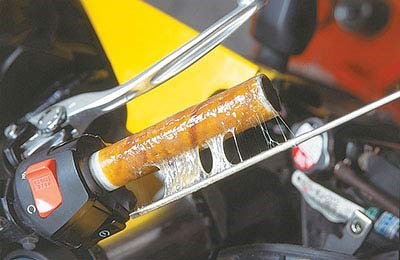
4. Care is needed to take off the old throttle grip. To prevent damage to the throttle tube, insert a thin screwdriver between the grip and tube and gently lift. There needs to be enough room to spray contact cleaner, or pour white spirit between them. This breaks down the glue and, after wiggling the screwdriver, the grip should just pull off.
5. With the bars squeaky clean, apply contact glue evenly around the length of the bar (only do one bar at a time). Apply with a metal screwdriver as it’s easier to wipe clean. Be careful not to get any glue between the throttle tube and metal handlebar. Remember to use the bigger diameter grip on the throttle side.
6. Ease the opening of the grip on to the bar and wriggle or push the grip into place. Don’t crease the grip because you could damage the wire elements within it. Make sure the grip is butted up against the end of the handlebar. Repeat the same glue application and fitting technique to the other bar.

7. When ordering heated grips ask if the grips come with open ends so the bar weights can be put back on. Don’t worry if they don’t because it’s easily sorted. Carefully cut a small penny-shaped hole in the end – what you don’t want to do is to accidentally cut through the grip and completely bugger up the wiring.
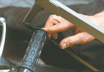
8. With the same care, enlarge the hole with small cuts to make it bigger until the metal bar can be seen. You might have to make this hole slightly bigger so the grip doesn’t rub on the bar and the throttle can be opened and closed freely. The left bar isn’t so critical – just lop off the end of the grip with a hacksaw.

9. More cutting may be involved when it comes to refitting the bar end-weights. As their screws are tightened and the weights locate into place, the grips may get in the way. In the case of the throttle grip this could interfere with the smooth opening and closing of the throttle. WD40 or grease between the throttle tube and bar will help.

10. The thermostat switch needs to be mounted within easy reach of a gloved hand. For switches with brackets supplied fit to the bars. If it is glued or Velcro-mounted try on the upper fairing lip near the tank, or on the clock surround. Cable-tie the wiring neatly along the bars so they don’t rub when the bars move.

11. Access the bike’s battery – usually under the seat. If the wires cannot be fed under the tank you’ll have to lift it slightly; get a friend to hold it up. Connect the wires directly to the battery with the right polarity as per the instructions. All wires and the inline fuse need to be held in place with tape or cable-ties. Refit the tank.
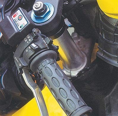
12. Before anything else retrace your steps and ensure all fasteners are done up tight. Now, with the engine running to save flattening the battery, switch on the heated grips. Turn the heat range to maximum and soon you’ll have toasty fingers. Then turn it down to minimum just to make sure the system works correctly. Bliss.
Find Your Heated Handgrips Here at a Trusted and Reliable Source >>>
Credit: CanyonChasers & Motorcyclenews
For more information about customizing your bikes, motorcycles, tons of the best OEM brands, personal watercrafts, atvs, parts, accessories, or maintenance tips please see our sponsor at: PartsPitStop.com .
#partspitstop #howto #handgrips #gripandrip #DIY #oemparts #aftermarketparts #oemaccessories #aftermarketaccessories
